Power & Connectivity
The Door & Gate Controller needs two things to come online: power and a network path to the internet. This page covers both, including the recommended PoE setup that delivers them over a single cable.
Power input
| Parameter | Value |
|---|---|
| Nominal input | 12V DC (socket marked 12V DC) |
| Accepted input range | 9V – 36V DC |
| Connector | 5.5 x 2.0 mm DC barrel socket |
| Polarity | Centre positive, outer sleeve negative |

Figure 1: Centre-positive polarity, as marked on the enclosure
Never power your door lock from the controller's supply. Locks must run from their own power supply, switched through the controller's relay — see the Relay Wiring Guide. Sharing a supply between the controller and an inductive lock can damage equipment.
Recommended: power over Ethernet (PoE)
The controller can be ordered with a PoE splitter, and we recommend powering the device this way: a single Ethernet run from a PoE switch (or injector) carries both data and power to the door, and the splitter breaks it out at the controller end.
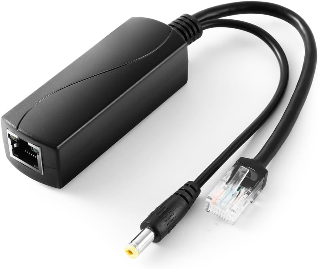
Figure 2: The optional PoE splitter — PoE IN port on the body, with a data lead (RJ45) and a 12V DC lead (5.5 x 2.1 mm barrel plug) for the controller

Figure 3: One Ethernet run carries data + power; the splitter feeds the controller's 1000M port and 12V DC socket
To connect:
- Run Ethernet from an IEEE 802.3af PoE switch port (or PoE injector) to the splitter's PoE IN port.
- Patch the splitter's LAN OUT port to the controller's 1000M Ethernet port with the short data lead.
- Plug the splitter's DC output lead (5.5 x 2.1 mm, centre positive) into the controller's 12V DC socket.
PoE splitter specifications
| Parameter | Value |
|---|---|
| Standard | IEEE 802.3af (15.4 W), also IEEE 802.3i/u/x |
| Data pass-through | 10/100/1000 Mbps (Gigabit) |
| PoE input | 37 – 57V DC (auto-detected from the PSE) |
| DC output | 12V 1A |
| DC plug | 5.5 x 2.1 mm, centre positive |
| Protection | Isolation circuit, short-circuit and overvoltage protection, 1500V isolation |
| Operating temperature | -20°C to 50°C |
The PoE splitter is an order option — skip it (or choose another power configuration) if you prefer to power the controller from a local 12V DC supply — for example, sharing a battery-backed cabinet supply with separate outputs. Any regulated 9–36V DC supply with the correct plug and polarity is acceptable; 12V is the standard configuration.
Wired network (all models)
- Use the 1000M port — it's the primary network interface and the one to use when hard-wiring to a switch or router. It's adaptive 10/100/1000M; a Cat6 cable is recommended.
- The 10/100M port is reserved — leave it unconnected in normal installations.
- The controller obtains its address via DHCP and makes outbound connections only. It reports in to the platform continuously; a device counts as online when it has reported within the last 5 minutes (see Adding a Door or Gate).
Ethernet is the most reliable connection method and is recommended for every install where a cable run is practical.
Wi-Fi (Wi-Fi and 4G models)
Wi-Fi as a primary connection is discouraged. Door and gate access is critical infrastructure — when the network drops, people can't get in. Hard-wired Ethernet is always the recommended approach when deploying a new installation; treat Wi-Fi as a backup/secondary path (much like the 4G option), and rely on it as the primary connection only where a cable run is genuinely impossible.
Wi-Fi models add dual-band Wi-Fi (2.4 GHz and 5 GHz) for sites where a cable run to the door isn't practical.
- Fit the supplied Wi-Fi antenna to the SMA connector before powering on.
- Position matters: avoid burying the controller (and its antenna) inside metal cabinets — see placement guidance.
- Full radio specifications are in Hardware Specifications.
4G backup (4G model)
The 4G model adds a cellular modem and SIM slot as a backup internet path:
- Insert a standard-size SIM into the SIM slot (chip contacts facing up). The controller automatically detects the SIM — no configuration is required on the device.
- Fit the supplied 4G/LTE antenna to its SMA connector before powering on.
- Automatic failover: if the controller's primary connection (Ethernet or Wi-Fi) loses internet connectivity, it automatically switches to 4G, and switches back when the primary connection is restored. Doors keep working through ISP outages, router reboots, and site network changes.
4G is a backup path, not a primary connection — pair it with Ethernet (or Wi-Fi) for normal operation. Supported LTE bands are listed in Hardware Specifications.
Antennas
| Model | Antennas |
|---|---|
| Standard | None |
| Wi-Fi | 1 x Wi-Fi/BT antenna (SMA) |
| 4G | 1 x Wi-Fi/BT antenna + 1 x 4G/LTE antenna (SMA) |
Always attach antennas before powering the device on, and hand-tighten them on the SMA connectors.
Related pages
- Relay Wiring Guide — wiring the relay to your lock
- Hardware Troubleshooting — power LED states, offline doors
- Hardware Specifications — electrical and wireless spec tables