Mounting & Dimensions
This page covers the physical installation of the Door & Gate Controller: enclosure, dimensions, and the two supported mounting methods. For wiring, see Power & Connectivity and the Relay Wiring Guide.
Appearance and structure
The controller is housed in a full metal enclosure with connectors on two opposite faces:
- Terminal panel — relay output block (plus reserved terminal blocks), indicator LEDs, buttons, and the antenna connector(s) on Wi-Fi/4G models.
- Connections panel — Ethernet ports, power socket, and the SIM slot (4G model).
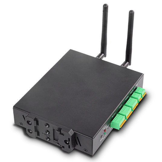
Figure 1: The controller's terminal side, with removable plug-in terminal blocks and the DIN rail clip fitted underneath
The relay and other terminals are plug-in screw terminal blocks — you can unplug a block, screw the wires down on the bench, and plug it back in. This makes lock wiring and later servicing much easier.
Dimensions
| Measurement | Value |
|---|---|
| Length | 170 mm |
| Width | 120 mm |
| Height | 30 mm |
| Enclosure | Full metal |
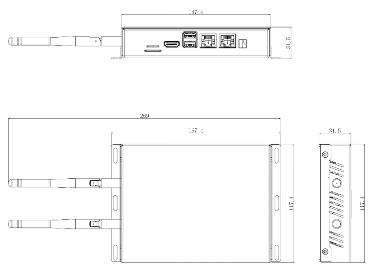
Figure 2: Overall dimensions (mm). Allow extra clearance for antennas on Wi-Fi/4G models and for cable bend radius at both panels.
Mounting
The controller supports two mounting methods. In both cases, mount it with the panels accessible — you'll want to see the indicator LEDs and reach the terminal blocks during commissioning.
DIN rail mounting
The controller clips onto a standard DIN rail using the DIN clip — ideal when installing in an equipment cabinet or on a backboard next to the lock power supply.
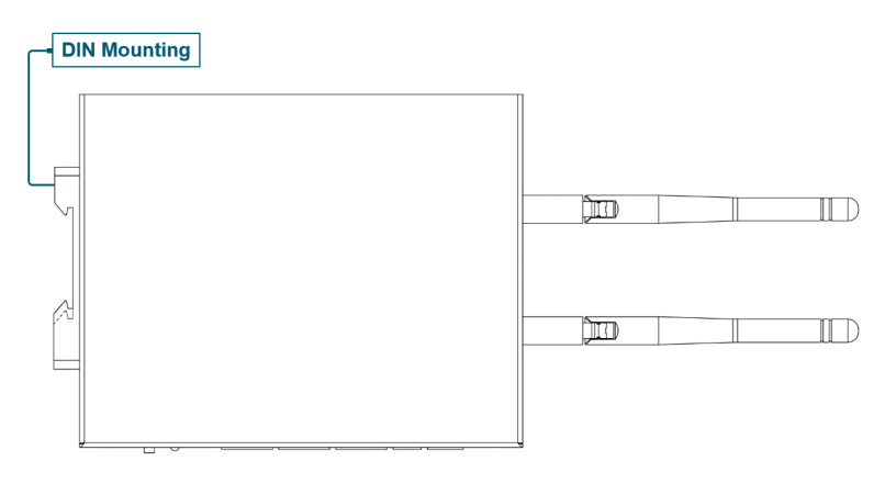
Figure 3: DIN rail mounting orientation
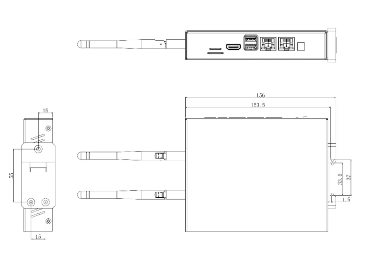
Figure 4: DIN clip mounting dimensions (mm)
Wall mounting
The controller can be screwed flat to a wall using wall-mounting ears.
Wall-mounting accessories are not included in the standard package — request them when ordering if you plan to wall-mount.
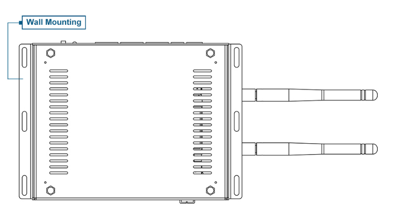
Figure 5: Wall mounting orientation
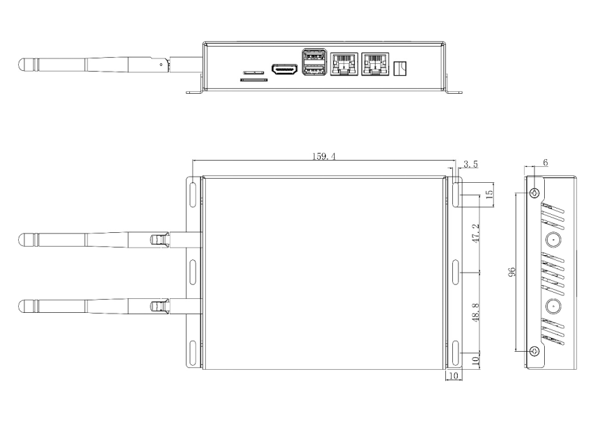
Figure 6: Wall-mount hole spacing (mm)
Placement guidance
- Secure side of the door. Install the controller on the protected side of the opening (e.g. comms room, ceiling void, riser) — never on the public side where the relay wiring could be tampered with.
- Within cable reach. Plan the runs before fixing the unit: relay cable to the lock, Ethernet to your switch (or the PoE splitter inline), and DC power.
- Environment. Operating temperature is -25°C to 50°C. The metal enclosure is not weatherproof — for outdoor gates, install the controller inside a weatherproof enclosure or nearby indoor space.
- Wi-Fi / 4G models. Fit the antenna(s) before powering on and keep them clear of large metal surfaces. If the controller lives inside a metal cabinet, signal will be significantly reduced — prefer Ethernet, or mount remote antennas outside the cabinet.
- Leave room to service. Terminal blocks unplug from the panel face; leave enough slack and clearance to do so.
Related pages
- Door & Gate Controller — models and panel layout
- Power & Connectivity — powering the unit once mounted
- Relay Wiring Guide — wiring to the lock