Door & Gate Controller
The Door & Gate Controller is the on-premise device at the heart of Door & Gate Access. It sits near each door or gate, connects to your network, and drives the locking hardware (electric strike, magnetic lock, gate motor trigger, etc.) through its built-in relay. Every unlock — from the mobile app, the admin dashboard, or an auto-unlock schedule — ends with this device switching its relay.
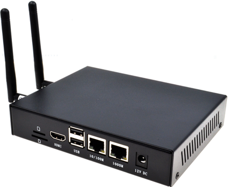
Figure 1: The Door & Gate Controller (Wi-Fi/4G model shown with antennas fitted)
The controller is an industrial-grade unit in a full metal enclosure, rated for installation in plant rooms, risers, ceiling voids, and other back-of-house spaces from -25°C to 50°C. It pairs with your facility using its serial number — see Adding a Door or Gate.
Models
The controller ships in three configurations. All three are identical apart from their connectivity options — same enclosure, same relay, same mounting.
| Model | Ethernet | Wi-Fi | 4G backup | Antennas included |
|---|---|---|---|---|
| Standard | Yes | — | — | None |
| Wi-Fi | Yes | Dual-band 2.4 GHz & 5 GHz | — | 1 x Wi-Fi antenna |
| 4G | Yes | Dual-band 2.4 GHz & 5 GHz | Yes (automatic failover) | 1 x Wi-Fi antenna, 1 x 4G/LTE antenna |
On the 4G model, the cellular link is a backup path: the controller automatically switches to 4G when its Ethernet/Wi-Fi connection loses internet connectivity, and switches back when it's restored. See Power & Connectivity.
What's in the box
- 1 x Door & Gate Controller
- (if ordered with the PoE option — recommended) 1 x PoE splitter — see Power & Connectivity
- (Wi-Fi and 4G models) 1 x 2.4 GHz/5 GHz Wi-Fi antenna
- (4G model) 1 x 4G/LTE antenna
The PoE splitter is an order option, not standard — choose it (recommended) or another power configuration when ordering, e.g. if you're powering the controller from a local DC supply. Wall-mounting brackets are not included by default — see Mounting & Dimensions.
Panel layout
The controller has connectors on two opposite faces: a terminal panel (relay output, indicator lights, buttons) and a connections panel (network, power, SIM).
Terminal panel
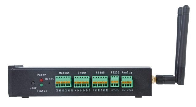
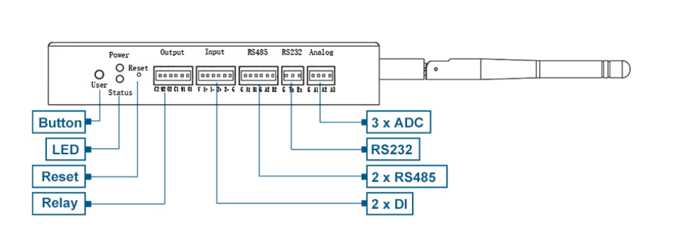
Figure 2: The terminal panel — the Output (relay) block is the only terminal block used by Door & Gate Access
| Item | Used by Door & Gate Access? |
|---|---|
| Output (relay terminals) | Yes — wires to your locking hardware. See the Relay Wiring Guide. |
| Power / Status LEDs | Yes — see Indicator lights below. |
| Reset button | Restarts the controller (recessed; press with a pin). |
| Input (DI), RS485, RS232, Analog (ADC) terminals | Reserved — not currently used by the Door & Gate Access application. They may be enabled in future updates or used by special implementation features. Leave them unwired. |
| User button | Reserved. |
Connections panel
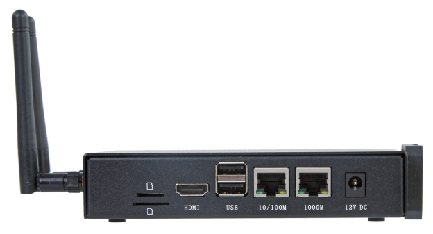
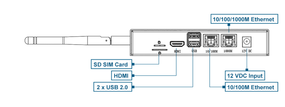
Figure 3: The connections panel — network and power
| Item | Used by Door & Gate Access? |
|---|---|
| 1000M Ethernet port | Yes — the primary network connection when hard-wiring to a switch or router. |
| 12V DC power socket | Yes — powered by the optional PoE splitter, or a local DC supply. |
| SIM card slot | 4G model only — takes a standard-size SIM. |
| 10/100M Ethernet port | Reserved. |
| HDMI, USB 2.0, SD slot | Reserved — not used in normal operation. |
| Antenna connectors (SMA) | Wi-Fi and 4G models — fit the supplied antenna(s) before powering on. |
Indicator lights
The controller has two indicator LEDs on the terminal panel:
| Indicator | State | Meaning |
|---|---|---|
| Power (red) | On | The device is powered. |
| Power (red) | Blinking | Power supply is abnormal — disconnect power immediately and check the supply. |
| Power (red) | Off | The device is not powered. |
| Status (green) | Blinking | The system started successfully and is reading/writing data. |
| Status (green) | Off | The device is not powered, or there is no data activity. |
If the lights don't match what you expect, see Hardware Troubleshooting.
Built-in sounder
The controller has an integrated buzzer used by Door & Gate Access for audible feedback:
- Door open sound — a short chirp whenever the relay toggles. Enable or disable it per door in the door's Configuration tab.
- Identify device — plays three medium beeps so you can find a specific controller on-site when several are installed close together.
Both are covered in Doors — no wiring is required for the sounder.
Serial number
Each controller's serial number is printed on the device label (with a QR code). You'll need it when pairing the controller with your facility.
Related pages
- Mounting & Dimensions — physical installation
- Power & Connectivity — PoE, Ethernet, Wi-Fi, and 4G
- Relay Wiring Guide — wiring the relay to your lock
- Hardware Specifications — full spec tables
- Adding a Door or Gate — pairing the controller with your facility